Electronic Thermostat
Mechanical thermostat has been around for a long time and has been used in industrial control, home appliances control and many other devices to measure and control the temperature of a certain processes. The sensor used usually is a bimetallic sensor that is make from two different metals that expand at different rates as they are heated up. These metal strips are bonded together and when the temperature rises, the strips will bend upward hence making connection to the contact of the circuit so that current can flow through the circuit.
As the temperature cools down, it will go back to its original position and disconnect the current from the circuit. By adjusting the strip and the contact, the temperature can be contolled. Most oven and air conditioners use this type of sensor. The mechanical thermostat is more widely used due to its lower cost compared to electronic thermostat.
The use of electronic thermostat is becoming more popular now as the cost of semiconductor continues to drop with the advancement of better fabrication and packaging processes. Many applications have switched to electronic control as the control of the temperature is more accurate, easier to control the desired temperature using digital technology, more reliable and interfacing with other devices.
This application note from Microchip uses a low cost 6 pin microcontroller in the design of electronic thermostat. The features of PIC10F204 are as shown below. One advantage is that it has the PDIP package which makes it easier for electronic hobbyists to do their own soldering.
- 256 Words Program Memory and 16 bytes Static RAM
- Wide Operating Voltage from 2.0V to 5.5V DC
- 3 I/O
- 1 comparator
- 25 mA source/sink current I/O
- 1 8-bit timers.
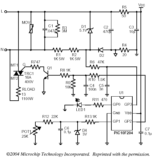
Among the learning experiences one gained from this projects are:
- Power supply is directly tapped from the AC lines voltage using a resistive based power supply. This makes the entire circuit live and one has to be careful when implementing this project. Ensure that no parts of the circuit is accessible to any user. Use a plastic enclosure to house the printed circuit board properly.
- The principles of triac is briefly discussed here. The use of zero crossing detection is useful as many applications use this method in their operations. Among them are light dimmer and motor control applications.
- Learn how to optimise the program code to make it efficient. Many programmers use long routines to accomplish a certain task when a few lines of codes would be sufficient. This experience needs to be learned as one hands on a project and repeatedly look into the code to make it shorter and efficient.
- Having learned the code, one can then modify and add temperature sensor to make it a close loop control. Display circuity and user interface can be added to the system by migration to a higher pin count microcontroller.
The full application note and source code of the Microcontroller Based Electronic Thermostat Project can be obtained from Microchip website.
ref: electronics-project-design.com/ElectronicThermostat.html


