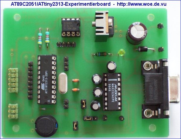
Using this programmer you can program the internal flash of the microcontroller AT89C2051 from Atmel. The AT89C2051 programmer is connected via the serial RS232 interface to a PC. In comparison with other programmers, you do not need a special software, a terminal program is sufficient. So there are no platform dependent limitations and it can be used universally.
Generally the programmer supports two different modes:
1. User mode: The desired operation Program (including Erase), Verify, Read or Lockbits can be selected via a BCD switch and started by pressing a button. The desired programming data will be transmitted or received in binary format via the RS232 interface. A special software data handshake is not required. A LED shows the current status.
2. Remote mode: In remote mode, the BCD switch and the button are not required, because the operations are selected via special remote commands from RS232 interface, followed by the binary data like in user mode. When the operation is finished, a status code is transmitted back, so it would also be possible to control the programmer with an own developed software.
1. User mode: The desired operation Program (including Erase), Verify, Read or Lockbits can be selected via a BCD switch and started by pressing a button. The desired programming data will be transmitted or received in binary format via the RS232 interface. A special software data handshake is not required. A LED shows the current status.
2. Remote mode: In remote mode, the BCD switch and the button are not required, because the operations are selected via special remote commands from RS232 interface, followed by the binary data like in user mode. When the operation is finished, a status code is transmitted back, so it would also be possible to control the programmer with an own developed software.

The schematic and the software can be downloaded here:
 Project files for hardware and software in ZIP format:
AT89C2051 programmer V1.1
For the hardware the freeware version of Eagle 3.55 is required. It is available for free from CadSoft.
 Schematic and component placement in GIF format:
Schematic of AT89C2051 programmer
Component placement of AT89C2051 programmer
 Printed circuit board:
There is a professionally manufactured unpopulated printed circuit board available for this project, named PRG2051.BRD
More information is available here: Printed circuit boards for WOE projects