Showing posts with label Lock. Show all posts

Friday, January 14, 2011

Construct an Electronic Lock

This project provides the schematic and the parts list needed to construct a very simple Electronic Lock. It is a simple project and will help the beginners to electronics to understand the one of the function of flip flops and their application.
A typical dual type D flip-flop features are as described below.

The MC14013B dual type D flip–flop is constructed with MOS P–channel and N–channel enhancement mode devices in a single monolithic structure. Each flip–flop has independent Data, (D), Direct Set, (S), Direct Reset, (R), and Clock (C) inputs and complementary outputs (Q and Q). These devices may be used as shift register elements or as type T flip–flops for counter and toggle applications.
• Static Operation
• Diode Protection on All Inputs
• Supply Voltage Range = 3.0 Vdc to 18 Vdc
• Logic Edge–Clocked Flip–Flop Design
Logic state is retained indefinitely with clock level either high or low; information is transferred to the output only on the positive–going edge of the clock pulse
• Capable of Driving Two Low–power TTL Loads or One Low–power Schottky TTL Load Over the Rated Temperature Range
• Pin–for–Pin Replacement for CD4013B


This is a pre determined hardwire type of combination lock that will trigger a relay in response to a right sequence of 4 numbers keyed in on the remote keypad. Pressing other keys will reset the electronic lock.

You can find the CK210 Electronic Lock kit here under the SURVEILLANCE AND SECURITY (SPY) category.

ref: electronics-project-design.com/ElectronicLock.html

Thursday, September 17, 2009

Digital Keypad Combination Lock


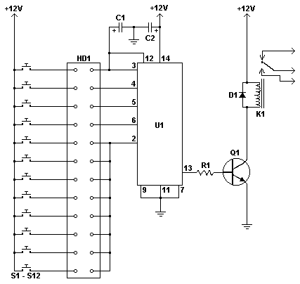
This simple circuit is the electronic version of the combination lock. Using the special purpose LS7220 digital lock IC, the circuit allows a 4 digit combination of your choice to activate a relay for a set period of time. This relay can then be used to trigger a lock solenoid, enable a starter button, open a motorized door, or many other tasks that require a momentary signal.

               
C1           1              1uF 25V Electrolytic Capacitor   
C2           1              220uF 25V Electrolytic Capacitor              
R1           1              2.2K 1/4W Resistor        
Q1          1              2N3904 NPN Transistor 2N2222
D1           1              1N4148 Rectifier Diode 1N4001-1N4007
K1           1              12V SPDT Relay Any appropriate relay with 12V coil
U1          1              LS7220 Digital Lock IC    
S1-S12   12           SPST Momentary Pushbutton    Keypad (see notes)
HD1       1              12 Position Header        
·  To set the combination, wire the appropriate switches to U1 pins 3, 4, 5 and 6 using the header. For example if S1 was connected to pin 3, S2 to pin 4, S3 to pin 5 and S4 to pin 6, the combination would be 1,2,3,4. Now wire all other unused switches across the header to pin 2 of U1. In this way you can create any 4 digit combination you want. Pin 2 is the reset pin, so connecting all unused keys to it assures that the entire combination must be reentered if an incorrect key is pressed.
·  When the appropriate combination is entered, the relay is activated for a period of time determined by C1. The 1uF capacitor specified in the parts list will result in an on-time of roughly 5 seconds. Increase the value of C1 to increase this time.
·  An easy way to make a keypad is to buy 12 PC board mount pushbuttons and then etch a PC board so that the buttons are in 4 rows of 3, similar to a telephone keypad. Place this in a case and then use a label maker or transfer letters to add your numbers to the tops of the pushbuttons. You can also use a pre made keypad but keep in mind that you need a pad which provides an output for each key. Most pads available have the keys connected to provide a row and column signal when they are pressed.
ref: aaroncake.net/Circuits/combolock.asp