
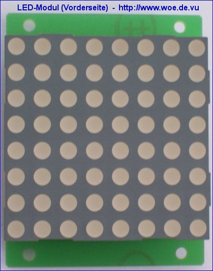
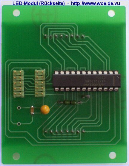
The LED moving font is built up of separate modules consisting of 64 LEDs each (8x8 matrix). The modules can be cascaced according to the desired size of the font. Each module is controlled by the LED display driver MAX7219 (or MAX7221) which can drive 64 LEDs. The display data is transferred serially to this display driver via the pins DIN, CLK and LOAD. The pin DOUT can be connected to the input DIN of the following display driver, all CLK and all LOAD pins are connected together. The datasheet is available on Maxim's homepage.
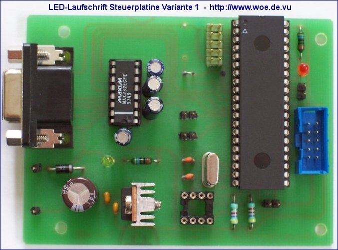
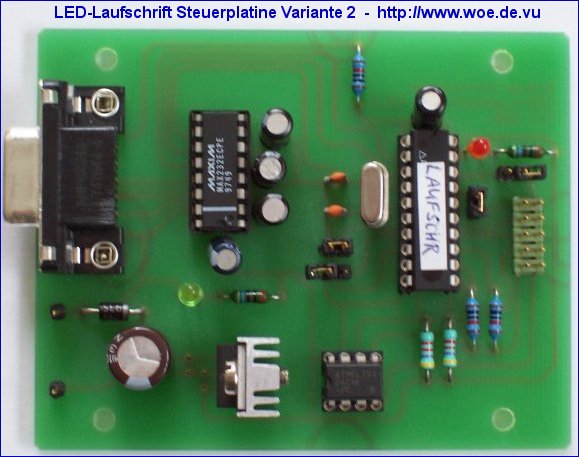
The modules are controlled by an 8051-compatible microcontroller AT89C51 (LED moving font controller variant 1) or AT89C2051 (LED moving font controller variant 2) from Atmel which provide 4 kB or 2kB flash memory on-chip. The LED display driver MAX 7219 CNG is available from Reichelt or Segor, a free sample can be ordered on the homepage of Maxim. The LED display driver is mounted together with a LED module (8x8 matrix) on the LED module PCB.
The display text is stored in a EEPROM. The text can be downloaded via a serial RS232 connection from a PC. From the PC a text file containing the text is sent. The baudrate can also be set to 600 Baud (via additional jumper), because some PCs have problems with hardware handshaking, which would be necessary at 1200 or 9600 Baud download speed. Dependent on the storage size of the EEPROM up to 2045 characters can be stored. It is also possible to store the text in the flash ROM of the microcontroller. But then it is necessary to reassemble the program code if the text is changed and to reprogram the flash ROM. If an EEPROM is used, changes of the text can be done easily via serial downloading. A maximum of 11 LED modules (each module consisting of 8x8 LEDs) can be used. The moving font is already working with 1 module.
Adjusting moving speed: in EEPROM-Mode, 255 speed values can be set. The selected value can be transmitted via serial interface and will be stored in a byte in EEPROM.
Adjusting moving speed: in EEPROM-Mode, 255 speed values can be set. The selected value can be transmitted via serial interface and will be stored in a byte in EEPROM.
The schematic and the software can be downloaded here:
 Project files for hardware and software in ZIP format:
LED moving font V2.3
For the hardware the freeware version of Eagle 3.55 is required. It is available for free from CadSoft.
 Schematic and component placement in GIF format:
LED moving font controller variant 1 (for AT89C51):
Schematic of LED moving font controller variant 1
Component placement of LED moving font controller variant 1
LED moving font controller variant 2(for AT89C2051):
Schematic of LED moving font controller variant 2
Component placement of LED moving font controller variant 2
LED module:
Schematic LED module
Component placement of LED module
 Printed circuit board:
There are professionally manufactured unpopulated printed circuit boards available for this project, named:
MAT_CON1.BRD (LED moving font controller variant 1 for AT89C51)
MAT_CON2.BRD (LED moving font controller variant 2 for AT89C2051)
LEDMODUL.BRD (PCB for 1 LED module TC23-11EWA)
More information is available here: Printed circuit boards for WOE projects
 Programmed microcontroller:
If you are interested in a programmed microcontroller, please send an email including the project name.
 Did you like this project?
So feel free to support WOE with a small donation. You will support the development of further free projects on this site. Thank you.
Suitable 8x8 LED dot matrix displays for the LED moving font:
For each LED module a 8x8 LED dot matrix display is required with common cathode columns and common anode rows. You can build the dot matrix displays with seperate LEDs on a universal PCB or you can use 8x8 LED dot matrix panels. A suitable type is the display TC23-11EWA manufactured by Kingbright, a suitable unpopulated PCB is available, look ahead. The color of this LED dot matrix display is red, but it is also available in different colors.
For each LED module a 8x8 LED dot matrix display is required with common cathode columns and common anode rows. You can build the dot matrix displays with seperate LEDs on a universal PCB or you can use 8x8 LED dot matrix panels. A suitable type is the display TC23-11EWA manufactured by Kingbright, a suitable unpopulated PCB is available, look ahead. The color of this LED dot matrix display is red, but it is also available in different colors.
Sources of supply for 8x8 LED dot matrix displays TC23-11EWA:
8x8 LED dot matrix displays TC23-11EWA (Manufacturer: Kingbright, color: red, technical data) are available via the distributors of Kingbright, e.g. menges electronic.
8x8 LED dot matrix displays TC23-11EWA (Manufacturer: Kingbright, color: red, technical data) are available via the distributors of Kingbright, e.g. menges electronic.
Ref: woe.onlinehome.de/e_projects.htm


