Showing posts with label Small Electronic Projects. Show all posts

Wednesday, October 14, 2009

Wire Loop Alarm

This circuit is a simple wire loop alarm that can be used in doorways, hallways, or any other place the tripwire will be broken by intruders. The circuit has a built in siren, but it can be replaced by a relay to drive an external siren, commercial alarm, etc.


R1           1              100K 1/2W 1% Resistor 
R2, R4    2              10K 1/2W 1% Resistor   
R3           1              1 Meg 1/2W 1% Resistor              
C1, C3    2              0.1uF Ceramic Disc Capacitor      
C2           1              0.01uF Ceramic Disc Capacitor   
IC1          1              4001UBE Quad 2-i/p NOR Gate 
Q1          1              MPSA14 Low Power NPN Transistor       
SIREN    1              Micro piezo siren 12V DC 150mA, 110dB @ 1M  
LOOP     1              See "Notes"      
MISC     1              Board, Wire, Socket For IC1       
  1. The loop can be any type of hookup wire, with a maximum resistance of about 90K. Using very thin wire (40AWG, for example) will make a very sensitive trip wire, but will shorten the distance it can be strung due to the high resistance.
  2. The siren can be replaced with a relay to drive external loads.
ref: aaroncake.net/Circuits/alarm1.asp

Sunday, October 4, 2009

Low Frequency Sinewave Generators


The two circuits below illustrate generating low frequency sinewaves by shifting the phase of the signal through an RC network so that oscillation occurs where the total phase shift is 360 degrees. The transistor circuit on the right produces a reasonable sinewave at the collector of the 3904 which is buffered by the JFET to yield a low impedance output. The circuit gain is critical for low distortion and you may need to adjust the 500 ohm resistor to achieve a stable waveform with minimum distortion. The transistor circuit is not recommended for practical applications due to the critical adjustments needed.
The op-amp based phase shift oscillator is much more stable than the single transistor version since the gain can be set higher than needed to sustain oscillation and the output is taken from the RC network which filters out most of the harmonic distortion. The sinewave output from the RC network is buffered and the amplitude restored by the second (top) op-amp which has gain of around 28dB. Frequency is around 600 Hz for RC values shown (7.5K and 0.1uF) and can be reduced by proportionally increasing the network resistors (7.5K). The 7.5K value at pin 2 of the op-amp controls the oscillator circuit gain and is selected so that the output at pin 1 is slightly clipped at the positive and negative peaks. The sinewave output at pin 7 is about 5 volts p-p using a 12 volt supply and appears very clean on a scope since the RC network filters out most all distortion occurring at pin 1.


ref: bowdenshobbycircuits.info/page8.htm#db.gif

Monday, September 28, 2009

3 Transistor Audio Amp (50 milliWatt)

Here is a little audio amplifier similar to what you might find in a small transistor radio. The input stage is biased so that the supply voltage is divided equally across the two complimentary output transistors which are slightly biased in conduction by the diodes between the bases. A 3.3 ohm resistor is used in series with the emitters of the output transistors to stabilize the bias current so it doesn't change much with temperature or with different transistors and diodes. As the bias current increases, the voltage between the emitter and base decreases, thus reducing the conduction. Input impedance is about 500 ohms and voltage gain is about 5 with an 8 ohm speaker attached. The voltage swing on the speaker is about 2 volts without distorting and power output is in the 50 milliwatt range. A higher supply voltage and the addition of heat sinks to the output transistors would provide more power. Circuit draws about 30 milliamps from a 9 volt supply.

ref: bowdenshobbycircuits.info/page8.htm#db.gif

Telephone Audio Interface

Audio from a telephone line can be obtained using a transformer and capacitor to isolate the line from external equipment. A non-polarized capacitor is placed in series with the transformer line connection to prevent DC current from flowing in the transformer winding which may prevent the line from returning to the on-hook state. The capacitor should have a voltage rating above the peak ring voltage of 90 volts plus the on-hook voltage of 48 volts, or 138 volts total. This was measured locally and may vary with location, a 400 volt or more rating is recommended. Audio level from the transformer is about 100 millivolts which can be connected to a high impedance amplifier or tape recorder input. The 3 transistor amplifier shown above can also be used. For overvoltage protection, two diodes are connected across the transformer secondary to limit the audio signal to 700 millivolts peak during the ringing signal. The diodes can be most any silicon type (1N400X / 1N4148 / 1N914 or other). The 620 ohm resistor serves to reduce loading of the line if the output is connected to a very low impedance.

ref: bowdenshobbycircuits.info/page8.htm#db.gif

Triangle and Squarewave Generator

Here is a simple triangle/squarewave generator using a common 1458 dual op-amp that can be used from very low frequencies to about 10 Khz. The time interval for one half cycle is about R*C and the outputs will supply about 10 milliamps of current. Triangle amplitude can be altered by adjusting the 47K resistor, and waveform offset can be removed by adding a capacitor in series with the output.

ref: bowdenshobbycircuits.info/page8.htm#db.gif

Thursday, September 24, 2009

Decibel Meter


The circuit below responds to sound pressure levels from about 60 to 70 dB. The sound is picked up by an 8 ohm speaker, amplified by a transistor stage and one LM324 op-amp section. You can also use a dynamic microphone but I found the speaker was more sensitive. The remaining 3 sections of the LM324 quad op-amp are used as voltage comparators and drive 3 indicator LEDs or incandescents which are spaced about 3dB apart. An additional transistor is needed for incandescent lights as shown with the lower lamp. I used 12 volt, 50mA lamps. Each light represents about a 3dB change in sound level so that when all 3 lights are on, the sound level is about 4 times greater than the level needed to light one lamp. The sensitivity can be adjusted with the 500K pot so that one lamp comes on with a reference sound level. The other two lamps will then indicate about a 2X and 4X increase in volume.
In operation, with no input, the DC voltage at pins 1,2 and 3 of the op-amp will be about 4 volts, and the voltage on the (+) inputs to the 3 comparators (pins 5,10,12) will be about a half volt less due to the 1N914 diode drop. The voltage on the (-) comparator inputs will be around 5.1 and 6.5 which is set by the 560 and 750 ohm resistors.
When an audio signal is present, the 10uF capacitor connected to the diode will charge toward the peak audio level at the op-amp output at pin 1. As the volume increases, the DC voltage on the capacitor and also (+) comparator inputs will increase and the lamp will turn on when the (+) input goes above the (-) input. As the volume decreases, the capacitor discharges through the parallel 100K resistor and the lamps go out. You can change the response time with a larger or smaller capacitor.
This circuit requires a well filtered power source, it will respond to very small changes in supply voltage, so you probably will need a large filter capacitor connected directly to the 330 ohm resistor. I managed to get it to work with an unregulated wall transformer power source, but I had to use 4700uF. It worked well on a regulated supply with only 1000uF.

ref: bowdenshobbycircuits.info/page8.htm#db.gif

FM Transmitter

Here is the schematic, PC board pattern, and parts placement for a low powered FM transmitter. The range of the transmitter when running at 9V is about 300 feet. Running it from 12V increases the range to about 400 feet. This transmitter should not be used as a room or telephone bug. 
 
 
C1           1              0.001uf Disc Capacitor   
C2           1              5.6pf Disc Capacitor        
C3,C4     2              10uf Electrolytic Capacitor           
C5           1              3-18pf Adjustable Cap  
R1           1              270 Ohm 1/8W Resistor 270 Ohm 1/4W Resistor
R2,R5,R6              3              4.7k 1/8W Resistor          4.7K 1/4W Resistor
R3           1              10k 1/8W Resistor            10K 1/4W Resistor
R4           1              100k 1/8W Resistor         100K 1/4W Resistor
Q1, Q2  2              2N2222A NPN Transistor               2N3904, NTE123A
L1, L2     2              5 Turn Air Core Coil         
MIC        1              Electret Microphone     
MISC     1              9V Battery Snap, PC Board, Wire For Antenna    

  1. L1 and L2 are 5 turns of 28 AWG enamel coated magnet wire wound with a inside diameter of about 4mm. The inside of a ballpoint pen works well (the plastic tube that holds the ink). Remove the form after winding then install the coil on the circuit board, being careful not to bend it.
  2. C5 is used for tuning. This transmitter operates on the normal broadcast frequencies (88-108MHz).
  3. Q1 and Q2 can also be 2N3904 or something similar.
  4. You can use 1/4 W resistors mounted vertically instead of 1/8 W resistors.
  5. You may want to bypass the battery with a .01uf capacitor.
  6. An antenna may not be required for operation.
ref: aaroncake.net/Circuits/fmtrans.asp

Thursday, September 17, 2009

12V to 120V Inverter


Have you ever wanted to run a TV, stereo or other appliance while on the road or camping? Well, this inverter should solve that problem. It takes 12 VDC and steps it up to 120 VAC. The wattage depends on which tansistors you use for Q1 and Q2, as well as how "big" a transformer you use for T1. The inverter can be constructed to supply anywhere from 1 to 1000 (1 KW) watts. 
C1, C2    2              68 uf, 25 V Tantalum Capacitor  
R1, R2    2              10 Ohm, 5 Watt Resistor              
R3, R4    2              180 Ohm, 1 Watt Resistor            
D1, D2   2              HEP 154 Silicon Diode    
Q1, Q2  2              2N3055 NPN Transistor (see "Notes")    
T1           1              24V, Center Tapped Transformer (see "Notes")               
MISC     1              Wire, Case, Receptical (For Output)        

  1. Q1 and Q2, as well as T1, determine how much wattage the inverter can supply. With Q1,Q2=2N3055 and T1= 15 A, the inverter can supply about 300 watts. Larger transformers and more powerful transistors can be substituted for T1, Q1 and Q2 for more power.
  2. The easiest and least expensive way to get a large T1 is to re-wind an old microwave transformer. These transformers are rated at about 1KW and are perfect. Go to a local TV repair shop and dig through the dumpster until you get the largest microwave you can find. The bigger the microwave the bigger transformer. Remove the transformer, being careful not to touch the large high voltage capacitor that might still be charged. If you want, you can test the transformer, but they are usually still good. Now, remove the old 2000 V secondary, being careful not to damage the primary. Leave the primary in tact. Now, wind on 12 turns of wire, twist a loop (center tap), and wind on 12 more turns. The guage of the wire will depend on how much current you plan to have the transformer supply. Enamel covered magnet wire works great for this. Now secure the windings with tape. Thats all there is to it. Remember to use high current transistors for Q1 and Q2. The 2N3055's in the parts list can only handle 15 amps each.
  3. Remember, when operating at high wattages, this circuit draws huge amounts of current. Don't let your battery go dead :-).
  4. Since this project produces 120 VAC, you must include a fuse and build the project in a case.
  5. You must use tantalum capacitors for C1 and C2. Regular electrolytics will overheat and explode. And yes, 68uF is the correct value. There are no substitutions.
  6. This circuit can be tricky to get going. Differences in transformers, transistors, parts substitutions or anything else not on this page may cause it to not function.
  7. If you want to make 220/240 VAC instead of 120 VAC, you need a transformer with a 220/240 primary (used as the secondary in this circuit as the transformer is backwards) instead of the 120V unit specified here. The rest of the circuit stays the same. But it takes twice the current at 12V to produce 240V as it does 120V.
 ref: aaroncake.net/Circuits/inverter.asp

Dual Polarity Power Supply


This dual polarity power supply is easy to build, requires few parts, and is adjustable from 0-15 volts. It is great for powering op amp circuits, as well as other circuits that require a dual supply voltage. 

C1, C2    2              2200uF 35V Electrolytic Capacitor             
C3, C4, C5, C7     4              1uF 35V Electrolytic Capacitor    
C6, C8    2              100uF 35V Electrolytic Capacitor               
R1, R4    2              5K Pot  
R2, R3    2              240 Ohm 1/4 W Resistor               
BR1        1              2A 30V Bridge Rectifier 
U1          1              LM317 Adjustable Positive Regulator     
U2          1              LM337 Adjustable Negative Regulator   
T1           1              30V Center Tapped 2 Amp Transformer
S1           1              SPST 2 Amp Switch         
MISC     1              Heatsinks For U1 And U2, Line Cord, Case, Knobs For Pots, Wire      
  1. Since this project operates from 120 (or 220, or 240, etc.) volts AC, it MUST be built inside a case.
  2. U1 and U2 get quite hot and will require heatsinks. A fan is usually not needed.
  3. You can, of course, add a volt and amp meter.
  4. U1 and U2 can only go down to a minimum of +-1.2V. If you need to go lower, you can add two 1N4003 diodes in series with the output of the regulator. The diodes drop about 0.6V each, which will allow the supply to go to 0. Note that this will also decrease your maximum output voltage by 1.2V.
ref: aaroncake.net/Circuits/supply3.asp

Touch Activated Light


The circuits below light a 20 watt lamp when the contacts are touched and the skin resistance is about 2 Megs or less. The circuit on the left uses a power MOSFET which turns on when the voltage between the source and gate is around 6 volts. The gate of the MOSFET draws no current so the voltage on the gate will be half the supply voltage or 6 volts when the resistance across the touch contacts is equal to the fixed resistance (2 Megs) between the source and gate. The circuit on the right uses three bipolar transistors to accomplish the same result with the touch contact referenced to the negative or ground end of the supply. Since the base of a bipolar transistor draws current and the current gain is usually less than 200, three transistors are needed to raise the microamp current level through the touch contacts to a couple amps needed by the light. For additional current, the lamp could be replaced with a 12 volt relay and diode across the coil.

ref: bowdenshobbycircuits.info/page8.htm#db.gif

Simple Polarity Tester


This tester can be used to check the polarity of any power source, and is therefore very useful when installing automotive equipment, alarm systems or anything else you can think of. Because this circuit is so simple and cheap, even frying one with an over voltage is not a big deal. 
R1           1              1K 1/4W Resistor            
D1           1              Green LED          
D2           1              Red LED               
D4, D5, D6, D7    4              1N4001 Silicon Diode     1N4004, 1N4005, 1N4007
MISC     1              Board, Wire, Case, Probes           

  1. To use the circuit, just connect your probes to the source under test. If D1 lights up, the left most probe (on the schematic) is connected to positive. The opposite is true if the left probe is negative. If both LEDs are on, the source being probed is AC.
  2. Be careful when using this tester not to probe a source greater than about 12V.
  ref: aaroncake.net/Circuits/polarity.asp

Digital Keypad Combination Lock


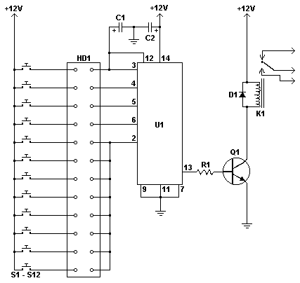
This simple circuit is the electronic version of the combination lock. Using the special purpose LS7220 digital lock IC, the circuit allows a 4 digit combination of your choice to activate a relay for a set period of time. This relay can then be used to trigger a lock solenoid, enable a starter button, open a motorized door, or many other tasks that require a momentary signal.

               
C1           1              1uF 25V Electrolytic Capacitor   
C2           1              220uF 25V Electrolytic Capacitor              
R1           1              2.2K 1/4W Resistor        
Q1          1              2N3904 NPN Transistor 2N2222
D1           1              1N4148 Rectifier Diode 1N4001-1N4007
K1           1              12V SPDT Relay Any appropriate relay with 12V coil
U1          1              LS7220 Digital Lock IC    
S1-S12   12           SPST Momentary Pushbutton    Keypad (see notes)
HD1       1              12 Position Header        
·  To set the combination, wire the appropriate switches to U1 pins 3, 4, 5 and 6 using the header. For example if S1 was connected to pin 3, S2 to pin 4, S3 to pin 5 and S4 to pin 6, the combination would be 1,2,3,4. Now wire all other unused switches across the header to pin 2 of U1. In this way you can create any 4 digit combination you want. Pin 2 is the reset pin, so connecting all unused keys to it assures that the entire combination must be reentered if an incorrect key is pressed.
·  When the appropriate combination is entered, the relay is activated for a period of time determined by C1. The 1uF capacitor specified in the parts list will result in an on-time of roughly 5 seconds. Increase the value of C1 to increase this time.
·  An easy way to make a keypad is to buy 12 PC board mount pushbuttons and then etch a PC board so that the buttons are in 4 rows of 3, similar to a telephone keypad. Place this in a case and then use a label maker or transfer letters to add your numbers to the tops of the pushbuttons. You can also use a pre made keypad but keep in mind that you need a pad which provides an output for each key. Most pads available have the keys connected to provide a row and column signal when they are pressed.
ref: aaroncake.net/Circuits/combolock.asp

Air Flow Detector

This simple circuit uses an incandescent lamp to detect airflow. With the filament exposed to air, a constant current source is used to slightly heat the filament. As it is heated, the resistance increases. As air flows over the filament it cools down, thus lowering it's resistance. A comparator is used to detect this difference and light an LED. With a few changes, the circuit can be connected to a meter or ADC to provide an estimation on the amount of air flow. 
R1           1              100 Ohm 1/4W Resistor               
R2           1              470 Ohm 1/4W Resistor               
R3           1              10k 1/4W Resistor          
R4           1              100K 1/4W Resistor       
R5           1              1K 1/4W Resistor            
C1           1              47uF Electrolytic Capacitor         
U1          1              78L05 Voltage Regulator              
U2          1              LM339 Op Amp
L1            1              #47 Incandescent lamp with glass removed (See "Notes")         
D1           1              LED        
MISC     1              Board, Wire, Sockets for ICs, etc.             
The glass will have to be removed from L1 without breaking the filament. Wrap the glass in masking tape and it in a vise. Slowly crank down until the glass breaks, then remove the bulb and carefully peel back the tape. If the filament has broken, you will need another lamp.
ref: aaroncake.net/Circuits/airflow.asp

Wednesday, September 16, 2009

Simplest shocker

This is the simpleest way to get harmles high volteges of an batery!

The transformer can be any mains transfomer(110-220V to 1-24V)

Whith the right transfomer it is posible to generate up to 2000V!!! (Don't wory its not dengerus becose of to low curents!)

these transformers normaly have 20-40:1 ratio so how can it make 2000V(200:1 ratio reqierd)?
Its becose some transformers have an good magnetic field breakdown efect(energy is storen in an magnetic field an then relesed as an high voletge spike)

If the releys coil resistanse is too big (inted in the reley the curent goes in the transfomer) the transistor must be hoked up in serial whith the reley coil (this will give lower performace)

I think this thing cod be hoked up whith an TV Flayback transformer too(to generate up to 20 000V)

A big cap (1000uF) parallel whith your power surce can inprove performance(its recomended if an lower curent power suply is used) 
ref: electro-tech-online.com/electronic-projects/12681-project-simplest-shocker.html

Water Activated Alarm


The circuit uses a 555 timer wired as an astable oscillator and powered by the emitter current of the BC109C. Under dry conditions, the transistor will have no bias current and be fully off. However as the probes get wet the transistor will conduct and sounding the alarm.

An On/Off switch is provided and remember to use a non-reactive metal for the probe contacts. Gold or silver plated contacts from an old relay may be used, however a cheap alternative is to wire alternate copper strips from a piece of veroboard. These will eventually oxidize over but as very little current is flowing in the base circuit, the higher impedance caused by oxidization is not important. No base resistor is necessary as the transistor is in emitter follower, current limit being the impedance at the emitter (the oscillator circuit).

 
ref: electro-tech-online.com/electronic-projects/51-water-activated-alarm.html

Hacked LED Mouse Light

Most of us have a bunch of these old mice laying around collecting dust. If you didn’t make some cool art with your mice last week here is another idea to recycle it into a cool project. This article will show you how to turn an ordinary mouse into a flashlight, perfect for looking into computer cases that always seem to be in the darkest corner of the room.

You will only need a few items for this hack.
* 360 Ohm resistor
* 9 Volt Battery Snap
* Heat Shrink (optional)
* White LED

This is the basic single LED version. A more elaborate version will be documented in the near future. Look at the bottom of this article for a sneak peak of the high end version. 

Look to see how to crack the mouse open. Most have some visible screws on the bottom. This one doesn’t…

After removing the glider pads the single screw is revealed. Removing this screw is all it takes to open the case.

This is a typical mouse. Lots of room and a big roller ball in the middle.

Start carefully removing the guts. Most of the components in this one were just slotted into place.

To make room for this mod the circuit board will be cut. This is also a convenient way to disconnect the switch that we will be using from the original circuit.

As you can see with the modified board installed there is now lots of room to play with.
A plastic fin on the top cover had to be trimmed to allow the battery to be installed. A simple snip of the side cutters is all it took.

There was also a small clearance issue with the side of the battery, we need this extra room since there will be a battery snap attached to the battery. Again the side cutters made easy work of the plastic fin.

I decided to use the original wire grommet as the LED hole. The wire diameter is smaller than the 5mm white LED that will be installed.

The drill press is overkill to enlarge the hole but it was handy.

The base of most LEDs have a flange, to accommodate this I simply used the tip of a soldering iron to melt away a some of the back of the grommet.

This mouse is designed quite well, the grommet slides right back into place with ease.

The LED is now slid into the grommet. Use a bit of hot glue if it is a loose fit, in this case it is held in there quite well with no glue.
Next we will solder some current limiting and one battery snap lead to the mouse switch. I am using the left click switch in this case. It is usually very easy to tell where to solder to since most mouse circuits use only N/O (normally open) switches which is what we need. If the switch has three connection you are usually safe to use the same ones that the original mouse circuit used.

Next I used some heat shrink to cover the resistor and bare wires.

Some wires are now connected to the LED and heat shrink is used to cover the bare wires. Red from the battery snap and the wire from the switch are used.

That is the entire circuit done. You can connect the battery now and give is a test.

Another shot from the side.

Slide the board back into place. Depending on the model of mouse you may need a bit of hot glue to hold it in place. For this one that was not required.

It is possible to have both switches control the single light, all you need to do is jumper the two switches together.

Since we are going to keep the roller ball in place make sure it will not rub on the wires when the unit is closed up.

Connect the battery. In this case it fit quite well, if the case is a bit larger you might need some foam to keep it from bouncing around inside.
Close the lid making sure not to pinch any wires.

That’s it, you now have a new flashlight.

Looks a bit like one of the old optical cordless mice from the front. In fact when it was sitting on the desk I have grabbed it a few times and wondered why the mouse cursor wasn’t moving on the screen…

Give it a push and make sure it works.

Now when you are working on your computer you can use a light that is cool and functional.

Here is a sneak peak of the next version of the LED mouse.
This is a three button mouse that controls four white LEDs and four UV LEDs. The UV LEDs are on the bottom and are used to check for counterfit money, cheques etc.
ref: hackedgadgets.com/2006/06/15/hacked-led-mouse-light

Triac light bulb flasher


This 800 W light bulb flasher operates directly off the line and needs no transformer. Power for the timer circuit is derived by limiting the current using a 330 nF capacitor (acts like a 9.6 k resistor at 50 Hz), rectifying with a full-wave rectifier composed of four diodes (you may also use a pre-made bridge rectifier instead of the diodes, of course, but make sure the voltage rating is 400 V, or 250 V RMS). Then the voltage is limited with a 9 V zener diode (almost any of this voltage will work), a 1 W type. The 100 µF capacitor filters the power, a 16 V rating may be a bit safer. Remember: if the zener diode fails, the capacitor will blow because it gets peaks of up to 330 V, although current-limited). In this configuration, the timer gives long pulses at 1.3 Hz.

Now there's one problem: we can't drive the triac directly, because the controlling voltage is not isolated from the line since there is no transformer. The easiest way to drive it is thus by using a triac optocoupler. The K3021 or MOC3021 is well suited for this purpose, as it works like a small triac and thus allows it to directly drive the gate of the larger triac. The coupler is connected to turn on when the timer outputs a low, so we get short pulses.

Please note that this only works with resistive loads like incandescent light bulbs or heaters. It does not work with fluorescent lamps (need a snubber network to do that).

Monday, September 14, 2009

Simple Lie Detector


Here's a simple lie detector that can be built in a few minutes, but can be incredibly useful when you want to know if someone is really telling you the truth. It is not as sophisticated as the ones the professionals use, but it works. It works by measuring skin resistance, which goes down when you lie.

 
 Here are the details of the specific parts you will need


Part Total Qty. Description Substitutions
  • R1 1 33K 1/4W Resistor
    R2 1 5K Pot
    R3 1 1.5K 1/4W Resistor
    C1 1 1uF 16V Electrolytic Capacitor
    Q1 1 2N3565 NPN Transistor
    M1 1 0-1 mA Analog Meter
    MISC 1 Case, Wire, Electrodes (See Nots)

Notes
1. The electrodes can be alligator clips (although they can be painful), electrode pads (like the type they use in the hospital), or just wires and tape.

2. To use the circuit, attach the electrodes to the back of the subjects hand, about 1 inch apart. Then, adjust the meter for a reading of 0. Ask the questions. You know the subject is lying when the meter changes.
ref: electro-tech-online.com/electronic-projects/40-simple-lie-detector.html

Simple AM Radio Receiver

Here's a very simple AM Radio circuit I've designed couple of years ago. Don't know whether anybody listen to AM stations anymore. But I still use it(maybe I wanted to listen to my own built radio lol..). The radio section is wired using a single transistor(BF494) and it was so amazing that an audible sound is recovered at the output which is faint though. It doesn't use any external antenna and the sensitivity/selectivity of the receiver is pretty good. However I used an amplifier(TA 7368P Toshiba, Low voltage) which drives an 8ohm/1W 4" speaker inside a box rocks the entire room with a high fidelity audio that is unbelievable and outperforms Superheterodyne ones in this regard . It is a reflex receiver.

The audio recovered at inductor L is rather strong comparing to ZN414 and free from oscillations.(I've never succeeded in building ZN414 which always give me annoying motorboating and chirping crappy I say!)

Using a flat ferrite bar antenna allows local reception for a pocket radio and a big rod antenna captures stations beyond 200miles! So it doesn't require an external wire antenna, adding it only helps in electrical noise catch.

Only critical part in the circuit is inductor L, its optimum value gives excellent results. Make rf parts close to the transistor. I made it on a 1.5" ultra small pcb. 2 x AA battery lasts very long.

Another important thing is that the radio is absolutely silent in between the stations - means no noise at all if no any electrical interferance which is a plus point over Superheterodyne receivers. It was so amazing to tune it during power failure period. So I'll call it a true radio


ref: electro-tech-online.com/electronic-projects/94129-simple-am-radio-receiver.html

Stun Gun

This stun gun is powered by a 9V battery. The transformer steps up the voltage to about 1800V (but with very low current). A 555 timer IC is used to generate a high-frequency output. A 1 MEG variable resistor can also be used at the output to drop the voltage, but this is optional. If you build this circuit, be careful, as it outputs a high voltage. Touching the output leads will induce a painful shock.


NOTE: Building stun guns can be very dangerous! Please use caution. 
ref: electro-tech-online.com/electronic-projects/38-stun-gun.html