Showing posts with label 555 timer. Show all posts

Tuesday, February 22, 2011

Electronic Timer Switch


Electronic Timer Switch
This electronic timer switch project is a good project to build to simulate the presence of occupants in a house. In these days when security is becoming more of a concern when no one is at home, having this device will deter the thief from breaking in. When power up, after 60 minutes, the relay will turn ON for 100 secs, OFF for the next 100 secs, and ON again for 100 secs before OFF again for the next 60 mins. This sequence will be repeated. A device such as a lamp that is connected to the relay will turn ON and OFF according to this timing.


Schematic Diagram

The schematic of the project is as shown below.


The core of this electronic timer switch project uses a CD4060B binary counter. The binary counter has 10 outputs and the counter are counted by configuring the oscillator. Every negative clock will trigger the counter of the IC internally.
The timing of the circuit is affected by resistor R3(1M ohm) and capacitor C2(0.1uF). By connecting the four outputs in an AND configuration, the transistor Q1 will only turn ON if all the 4 outputs are in logic "1". If any of the logic is "0", the transistor will remain OFF.
For a complete cycle, the transistor will be ON twice when the output at pin 15, QJ goes to logic "1" and "0" twice when the other outputs QL, QM and QN remain at "1". When this happen, the relay K1 will switch status accordingly. The timing of the switching can be changed by changing the resistor values R2, R3 and C2. Download the data sheet of CD4060B from Texas Instrument website for more details.
Note that since the oscillator is not using crystal, the timing may not be as accurate compared to the ideal calculation. In most cases, fine tuning the resistor and capacitor are good enough to make this project a success. To check whether the circuit is working, connect a LED in series with a 390 ohm resistor at output QD. It will flash ON and OFF as the oscillator oscillates.


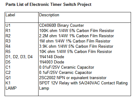
Parts List
ref: electronics-project-design.com/electronictimerswitch.html


Tuesday, February 8, 2011

Time Delay Circuit - using 555 Timer

Time Delay Circuit
In the design of analog circuits, there are times when you would need to delay a pulse that came into a circuit before being used for the next process. This time delay circuit uses a 555 timer to delay a pulse that comes in to a maximum time of 75 seconds. The timing of the delay can also be changed by changing the resistor value of VR1 and the capacitor value of E based on the time delay formula of t=0.69RC.
In order for the output to go high, the reset pin of 555 timer (pin 4) must be high and the TRIGGER pin (pin 2) voltage level must be below a third of the level of the power supply to the IC. When there is no pulse being applied to the input, transistor Q1 will turn ON and capacitor E is charged.


Once a pulse is applied to the input, transistor Q1 will turn OFF and pin 4 reset pin is held to high. This caused the capacitor E1 to be discharged through VR1 resistor. The time delay will depend on the discharged of capacitor E to a third of the supply before the output of 555 goes high. Experiment with different values of VR1 and E to get different time delay.
If the maximum value of potentiometer is set to 5M ohm, the time delay of the pulse will be 75 seconds.


Parts List


ref: electronics-project-design.com/timedelaycircuit.html

Constructional Countdown Timer Project using 555 Timer

ntroduction to Countdown Timer
In this Countdown Timer project, a 555 IC, a counter IC and a transistor switch to activate a relay either ON/OFF (mode selected by a jumper) as soon as the counting period is over. The circuit consists of an oscillator, a ripple counter and two switching transistors.

Oscillator
The 555 is configured in the standard astable oscillator circuit designed to give a square wave cycle at a period of around 1 cycle/sec. A potentiometer is included in the design so the period can be set to exactly 1 second by timing the LED flashes. A jumper connection is provided so the LED can be turned off. As soon as power is applied to the circuit counting begins. The output pulse from pin 3 of the 555 is fed to a the clock input pin 10 of the 14-stage binary ripple counter, the 4020 (or 14020.)

Ripple Counter
The counter output wanted is set by a jumper. Ten counter outputs are available: 8/16/32/64/128/256/512/1024/4096 and 8192 counts. If the 555 is set to oscillate at exactly 1.0Hz by the on-board trimpot then the maximum timer interval which can be set is 8192 seconds (just over 2 hours.) At the end of the counting of the countdown timer period a pulse is output on the pin with the jumper on it. The 14020 ripple counter advances its count on each negative transistion of the clock pulse from the 555. So for each output cycle of low-high-low-high the count is advanced by two. It can be set to an zero state (all outputs low) by a logic high applied to pin 11.
In this circuit C3, R4 and D1 are arranged as a power-on reset. When power is applied to the circuit C3 is in a discharged state so pin 11 will be pulled high. C3 will quickly charge via R4 and the level at pin 11 falls thus enabling the counter. The 14020 then counts clock pulses until the selected counter output goes high. D1 provides a discharge path for C3 when the power is disconnected.
You can change the components values of R1 and C1 to set the 555 count frequency to more than 1.0 Hz. If you change the count to 10 seconds then a maximum timer delay of 81920 seconds, or 22.7 hours, can be obtained.
Transistors
The output from the 4020 goes to a transistor switch arrangement. Two BC547 are connected so that either switching option for the relay is available. A jumper sets the option. The relay can turn ON when power and counting start then turn OFF after the count period, or it can do the opposite. The relay will turn ON after the end of the count period and stay on so long as power is supplied to the circuit. Note that the reset pin of the 555 is connected to the collector of Q1. This enables the 555 during the counting as the collector of Q1 is pulled low.

Schematic Diagram


Parts List


ref: electronics-project-design.com/CountdownTimer.html


Thursday, January 27, 2011

Auto Shut Off Tone Generator


Auto Shut Off Tone Generator
In this auto shut off tone generator project, once the switch to the 9V power supply is connected, the alarm will trigger at a frequency of approximately 1.27 kHz. It will remain ON for a duration of approximately 170 seconds or 2.8 minutes before it stopped. This is a typical home burglar alarm system
of which once the alarm is triggered ON, it will not be shut OFF until the duration of time set has elapsed. This project is useful when built as one can carry it along wherever one goes or placed it in a vehicle. In times of emergency, one can easily switched ON the switch and the loud speaker will emit a loud sound that will frighten the uninvited guest.

Schematic Diagram
The schematic of the tone generator is as shown below.


It is based on two 555 timer ICs or one single 556 timer IC(which contains two 555 timers). In this schematic, two 555 timers are used. U2 is configured as a timer in astable mode. Once triggered, it will emit a frequency from its output at pin 3 that will drive a Q1 transistor. Q1 transistor will turn ON and OFF according to the frequency of the circuit. It will in turn used to drive a 8 ohm loud speaker to emit a loud audible sound.
The astable frequency of circuit U2 is given by the formula of 555 timer as shown below.

f = 1.44/[47K + 2(33K)][10nF]

= 1.27 kHz


The frequency of the sound can be adjusted by changing the values of R3= 47K, R4= 33K and capacitor C1=10nF. Change the values of these components and by using the formula for astable mode, the frequency of the sound can be obtained.

U1 circuit is used as a delay circuit which is configured as a monostable mode. It is a one shot multivibrator that will generate a pulse at its output at pin 3 which will disable the astable circuit U1. In this circuit, pin 2 of U1 will go to logic 0 when the power supply is connected via the capacitor E1 and hence circuit U2 is immediately triggered.
The pulse duration of the monostable circuit is given by the formula:

T = 1.1(330K)(470uF)

= 170 seconds

Once this timing is up, it the pulse output will disable the astable circuit of U2.


Tone Generator Parts List


ref: electronics-project-design.com/ToneGenerator.html


Sunday, November 8, 2009

Police Siren Project


This police siren simulated electronic project uses two 555 timers IC to generate a sound similar to the police siren. A single 556 timer IC which consists of two 555 timers can also be used. In this circuit, both of the timers are configured as astable circuit. The first timer is configured as a square wave close to 1 Hz astable oscillator. The output of this timer is used to feed the control voltage of the second timer where it is subjected to frequency modulation. This frequency modulation will generate a tone similar to the siren used by the police. The frequency of this tone generator can be varied by changing the value of potentiometer VR1. When set to its maximum value of 220k ohm, it will have a tone frequency of approximately 320 Hz.
Schematic Diagram
The schematic of the project is as shown below.


When S1 is switched ON, the circuit will be powered ON and U1 will start to oscillate at a frequency given by the formula:

f = 1.44/[(R1 + 2R2)(E1)]

= 1.44/[(10 + 2*82)(10)] Hz

= 0.8 Hz


This output frequency from pin 3 of U1 is fed into pin 5 of U2 where it is subjected to frequency modulation through resistor 10K. The tone generated can be varied by changing the values of potentiometer VR1. Experiment with the sound and settle with the best sound of your choice. The output of U2 is used to drive a power transistor which in turn drives an 8 ohm speaker. Diode D2 is used to prevent the damage of transistor Q1 due to the back emf generated by the speaker during the ON/OFF driving of the speaker.

Parts List
The parts list of the project is as shown below.


ref:  electronics-project-design.com/PoliceSiren.html

Timer

Introduction
Timer circuit has been used in many projects and there are basically 2 types that are used these days. One of them is the use of analog RC circuit where charging of the capacitor circuit determined the T(time) of the circuitry. This type of circuitry has larger tolerance and is used in applications where the T is not so critical as the T is affected by the tolerance of the RC components used.
The other is the use of crystal or ceramic resonators together with microprocessor, microcontroller or application specific integrated circuit that need higher precision T in the tolerance of up to 5 ppm (parts per million).


555 IC
One commonly used circuit is the 555 IC which is a highly stable controller capable of producing timing pulses. With a monostable operation, the T(time) delay is controlled by one external resistor and one capacitor. With an astable operation, the frequency and duty cycle are accurately controlled by two external resistors and one capacitor. The application of this integrated circuit is in the areas of PRECISION TIMING, PULSE GENERATION, TIMING DELAY GENERATION and SEQUENTIAL TIMING.
A typical 555 IC block diagram is as shown below.


Monostable Operation
Figure below shows the monostable operation of a 555 IC.


In this mode, the device generates a fixed pulse whenever the trigger voltage falls below Vcc/3. When the trigger pulse voltage applied to pin 2 falls below Vcc/3 while the its output is low, its internal flip-flop turns the discharging transistor Tr off and causes the output to become high by charging the external capacitor C1 and setting the flip-flop output at the same instant. The voltage across the external capacitor C1, VC1 increases exponentially with the time constant T=RA*C1 and reaches 2Vcc/3 at td=1.1RA*C1. Hence, capacitor C1 is charged through resistor RA. The greater the time constant RA*C1, the longer it takes for the VC1 to reach 2Vcc/3. In other words, the time constant RA*C1 controls the output pulse width. When the applied voltage to the capacitor C1 reaches 2Vcc/3, the comparator on the trigger terminal resets the flip-flop, turning the discharging transistor Tr on. At this time, C1 begins to discharge and its output goes to low.
Astable Operation


An astable operation is achieved by configuring the circuit as shown above. In the astable operation, the trigger terminal and the threshold terminal are connected so that a self-trigger is formed, operating as a multivibrator. When its output is high, its internal discharging transistor Tr turns off and the VC1 increases by exponential function with the time constant (RA+RB)*C. When the VC1, or the threshold voltage, reaches 2Vcc/3, the comparator output on the trigger terminal becomes high, resetting the F/F and causing its output to become low. This in turn turns on the discharging transistor Tr and the C1 discharges through the discharging channel formed by RB and the discharging transistor Tr. When the VC1 falls below Vcc/3, the comparator output on the trigger terminal becomes high and the timer output becomes high again. The discharging transistor Tr turns off and the VC1 rises again. The frequency of oscillation is given as below.


ref: electronics-project-design.com/Timer.html

Monday, September 28, 2009

Construct a 6-15V Alarm

This project provides the schematic and the parts list needed to construct a very simple Alarm. This is a simple project and will help the beginners to electronics to understand one of the functions of 555 timers and one of their application. 556 timers has 2 of 555 timers.
General Description
The LM556 Dual timing circuit is a highly stable controller capable of producing accurate time delays or oscillation. The 556 is a dual 555. Timing is provided by an external resistor and capacitor for each timing function. The two timers operate independently of each other sharing only VCC and ground. The circuits may be triggered and reset on falling waveforms. The output structures may sink or source 200mA.
Features
a) Direct replacement for SE556/NE556
b) Timing from microseconds through hours
c) Operates in both astable and monostable modes
d) Replaces two 555 timers
e) Adjustable duty cycle
f) Output can source or sink 200mA
g) Output and supply TTL compatible
h) Temperature stability better than 0.005% per °C
i) Normally on and normally off output

Applications
a) Precision timing
b) Pulse generation
c) Sequential timing
d) Time delay generation
e) Pulse width modulation
f) Pulse position modulation
g) Linear ramp generator

The Connection diagram of a typical LM556 Dual timer is as shown below.


You will learn what 110dB of alarm sounds like. The piezo elements is set to oscillate around their resonant frequency. The sound generated is very loud and it can hurt your ears, so do be careful.

You can find the CK216 6-15V Alarm Module kit here under the SURVEILLANCE AND SECURITY (SPY) category.

ref: electronics-project-design.com/Alarm.html

Analog Timing Light Project


Timing Light Project

This analog timing light project uses RC circuit as a delay OFF timer to control the duration an incandescent light turns ON. When the accuracy of a timer is not critical, the use of RC circuit is a good choice as it is more cost effective and simple. Once the normally open switch SW is pressed, the light will turn ON for a duration of 10 - 20 seconds before it turns OFF. The duration of the turn ON time can be varied by varying the values of R1, R2 and E1.
Schematic Diagram
The schematic of the project is as shown below.


When SW is pressed, the base of the transistor Q1 is forward bias and it turns ON. This turns ON the 12V relay that is connected to the transistor. The contact of the relay RLY must be able to withstand the current of the load. At the same time, the electrolytic capacitor E1 is being charged to a voltage of approximately 0.7V.
Once SW is released, E1 will discharged through resistor R2 and the base of the transistor. After some time, When the voltage across E1 drops to approximately 0.5V, the transistor will turn OFF. This in turn will cause the relay to turn OFF and the incandescent light will turn OFF. The timing of the turn OFF can be changed by changing the values of E1, R1 and R2.

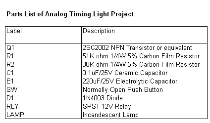
Parts List
The parts list of the project is as shown below.


ref: electronics-project-design.com/TimingLight.html

Wednesday, September 16, 2009

Water Activated Alarm


The circuit uses a 555 timer wired as an astable oscillator and powered by the emitter current of the BC109C. Under dry conditions, the transistor will have no bias current and be fully off. However as the probes get wet the transistor will conduct and sounding the alarm.

An On/Off switch is provided and remember to use a non-reactive metal for the probe contacts. Gold or silver plated contacts from an old relay may be used, however a cheap alternative is to wire alternate copper strips from a piece of veroboard. These will eventually oxidize over but as very little current is flowing in the base circuit, the higher impedance caused by oxidization is not important. No base resistor is necessary as the transistor is in emitter follower, current limit being the impedance at the emitter (the oscillator circuit).

 
ref: electro-tech-online.com/electronic-projects/51-water-activated-alarm.html

Triac light bulb flasher


This 800 W light bulb flasher operates directly off the line and needs no transformer. Power for the timer circuit is derived by limiting the current using a 330 nF capacitor (acts like a 9.6 k resistor at 50 Hz), rectifying with a full-wave rectifier composed of four diodes (you may also use a pre-made bridge rectifier instead of the diodes, of course, but make sure the voltage rating is 400 V, or 250 V RMS). Then the voltage is limited with a 9 V zener diode (almost any of this voltage will work), a 1 W type. The 100 µF capacitor filters the power, a 16 V rating may be a bit safer. Remember: if the zener diode fails, the capacitor will blow because it gets peaks of up to 330 V, although current-limited). In this configuration, the timer gives long pulses at 1.3 Hz.

Now there's one problem: we can't drive the triac directly, because the controlling voltage is not isolated from the line since there is no transformer. The easiest way to drive it is thus by using a triac optocoupler. The K3021 or MOC3021 is well suited for this purpose, as it works like a small triac and thus allows it to directly drive the gate of the larger triac. The coupler is connected to turn on when the timer outputs a low, so we get short pulses.

Please note that this only works with resistive loads like incandescent light bulbs or heaters. It does not work with fluorescent lamps (need a snubber network to do that).