Tuesday, September 29, 2009

Microcontroller Based Electronic Thermostat Project

Electronic Thermostat
Mechanical thermostat has been around for a long time and has been used in industrial control, home appliances control and many other devices to measure and control the temperature of a certain processes. The sensor used usually is a bimetallic sensor that is make from two different metals that expand at different rates as they are heated up. These metal strips are bonded together and when the temperature rises, the strips will bend upward hence making connection to the contact of the circuit so that current can flow through the circuit.
As the temperature cools down, it will go back to its original position and disconnect the current from the circuit. By adjusting the strip and the contact, the temperature can be contolled. Most oven and air conditioners use this type of sensor. The mechanical thermostat is more widely used due to its lower cost compared to electronic thermostat.
The use of electronic thermostat is becoming more popular now as the cost of semiconductor continues to drop with the advancement of better fabrication and packaging processes. Many applications have switched to electronic control as the control of the temperature is more accurate, easier to control the desired temperature using digital technology, more reliable and interfacing with other devices.
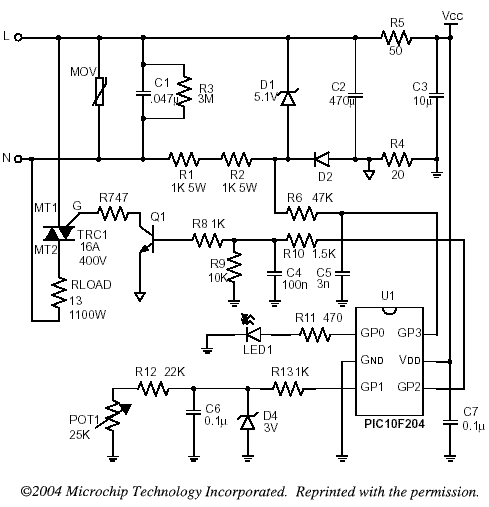
This application note from Microchip uses a low cost 6 pin microcontroller in the design of electronic thermostat. The features of PIC10F204 are as shown below. One advantage is that it has the PDIP package which makes it easier for electronic hobbyists to do their own soldering.

  • 256 Words Program Memory and 16 bytes Static RAM
  • Wide Operating Voltage from 2.0V to 5.5V DC
  • 3 I/O
  • 1 comparator
  • 25 mA source/sink current I/O
  • 1 8-bit timers.


Among the learning experiences one gained from this projects are:
  • Power supply is directly tapped from the AC lines voltage using a resistive based power supply. This makes the entire circuit live and one has to be careful when implementing this project. Ensure that no parts of the circuit is accessible to any user. Use a plastic enclosure to house the printed circuit board properly.
  • The principles of triac is briefly discussed here. The use of zero crossing detection is useful as many applications use this method in their operations. Among them are light dimmer and motor control applications.
  • Learn how to optimise the program code to make it efficient. Many programmers use long routines to accomplish a certain task when a few lines of codes would be sufficient. This experience needs to be learned as one hands on a project and repeatedly look into the code to make it shorter and efficient.
  • Having learned the code, one can then modify and add temperature sensor to make it a close loop control. Display circuity and user interface can be added to the system by migration to a higher pin count microcontroller.

The full application note and source code of the Microcontroller Based Electronic Thermostat Project can be obtained from Microchip website.

ref: electronics-project-design.com/ElectronicThermostat.html
Monday, September 28, 2009

Construct a two station Intercom

This intercom project provides the schematic and the parts list needed to construct a very simple wired two station Intercom. This project will help beginners to electronics understand one of the application of operational amplifers(OP AMP). In this case, the LM 386 operational amplifier is configured as an amplifier.
LM386 Low Voltage Audio Power Amplifier
The LM386 is a power amplifier designed for use in low voltage consumer applications. The gain is internally set to 20 to keep external part count low, but the addition of an external resistor and capacitor between pins 1 and 8 will increase the gain to any value from 20 to 200. The inputs are ground referenced while the output automatically biases to one-half the supply voltage. The quiescent power drain is only 24 milliwatts when operating from a 6 volt supply, making the LM386 ideal for battery operation.
Features
a) Battery operation
b) Minimum external parts
c) Wide supply voltage range: 4V–12V or 5V–18V
d) Low quiescent current drain: 4mA
e) Voltage gains from 20 to 200
f) Ground referenced input
g) Self-centering output quiescent voltage
h) Low distortion: 0.2% (AV = 20, VS = 6V, RL = 8W, PO = 125mW, f = 1kHz)
i) Available in 8 pin MSOP package

Applications
a) AM-FM radio amplifiers
b) Portable tape player amplifiers
c) Intercoms
d) TV sound systems
e) Line drivers
f) Ultrasonic drivers
g) Small servo drivers
h) Power converters


Those who are adventurous can also configure one of them to be permanently ON which means it can be used as a remote listening microphone by just a simple soldering of the 2 points of the circuit.
You can find the CK204 Two Station Intercom kit here under the SURVEILLANCE AND SECURITY (SPY) category.

ref: electronics-project-design.com/Intercom.html

Construct a 6-15V Alarm

This project provides the schematic and the parts list needed to construct a very simple Alarm. This is a simple project and will help the beginners to electronics to understand one of the functions of 555 timers and one of their application. 556 timers has 2 of 555 timers.
General Description
The LM556 Dual timing circuit is a highly stable controller capable of producing accurate time delays or oscillation. The 556 is a dual 555. Timing is provided by an external resistor and capacitor for each timing function. The two timers operate independently of each other sharing only VCC and ground. The circuits may be triggered and reset on falling waveforms. The output structures may sink or source 200mA.
Features
a) Direct replacement for SE556/NE556
b) Timing from microseconds through hours
c) Operates in both astable and monostable modes
d) Replaces two 555 timers
e) Adjustable duty cycle
f) Output can source or sink 200mA
g) Output and supply TTL compatible
h) Temperature stability better than 0.005% per °C
i) Normally on and normally off output

Applications
a) Precision timing
b) Pulse generation
c) Sequential timing
d) Time delay generation
e) Pulse width modulation
f) Pulse position modulation
g) Linear ramp generator

The Connection diagram of a typical LM556 Dual timer is as shown below.


You will learn what 110dB of alarm sounds like. The piezo elements is set to oscillate around their resonant frequency. The sound generated is very loud and it can hurt your ears, so do be careful.

You can find the CK216 6-15V Alarm Module kit here under the SURVEILLANCE AND SECURITY (SPY) category.

ref: electronics-project-design.com/Alarm.html

Analog Timing Light Project


Timing Light Project

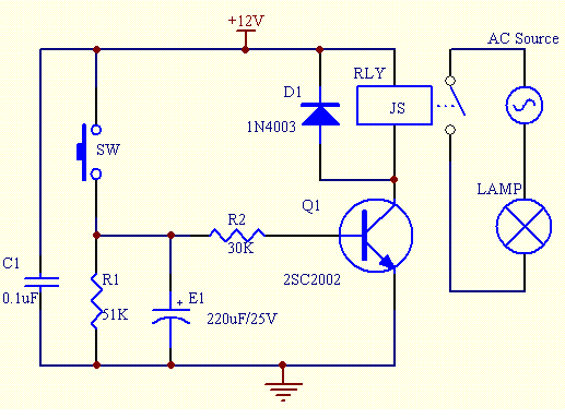
This analog timing light project uses RC circuit as a delay OFF timer to control the duration an incandescent light turns ON. When the accuracy of a timer is not critical, the use of RC circuit is a good choice as it is more cost effective and simple. Once the normally open switch SW is pressed, the light will turn ON for a duration of 10 - 20 seconds before it turns OFF. The duration of the turn ON time can be varied by varying the values of R1, R2 and E1.
Schematic Diagram
The schematic of the project is as shown below.


When SW is pressed, the base of the transistor Q1 is forward bias and it turns ON. This turns ON the 12V relay that is connected to the transistor. The contact of the relay RLY must be able to withstand the current of the load. At the same time, the electrolytic capacitor E1 is being charged to a voltage of approximately 0.7V.
Once SW is released, E1 will discharged through resistor R2 and the base of the transistor. After some time, When the voltage across E1 drops to approximately 0.5V, the transistor will turn OFF. This in turn will cause the relay to turn OFF and the incandescent light will turn OFF. The timing of the turn OFF can be changed by changing the values of E1, R1 and R2.

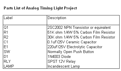
Parts List
The parts list of the project is as shown below.


ref: electronics-project-design.com/TimingLight.html

HVAC Thermostat


Introduction To HVAC Thermostat

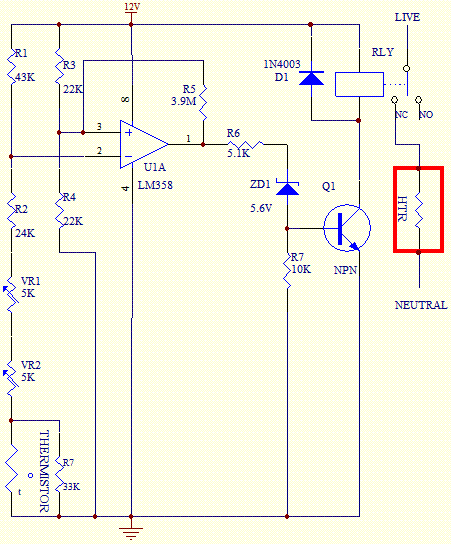
HVAC thermostat has been one of the common device used in residential and industrial buildings to control the temperature of a space be it a warehouse, a room, a hall or an office. This thermostat project will focus on the heating control of a space that uses electric heater as its source of heating. It basically consists of a comparator that controls the ON and OFF of the electric heater based on the sensor temperature.
The control of the fan speed is usually hardwired with two speed or three speed motors and is incorporated into the thermostat. The temperature range of this thermostat is from 5 Celcius to 30 Celcius with a tolerance of approximately 3 degree Celcius. Hence, only non critical tolerance control of temperature control such as a room can be used.

Circuit Description
The circuit diagram shows the configuration of the HVAC thermostat. The LM358 Op Amp is used as a comparator to sense the inputs of the reference voltage (PIN 3) and room temperature (PIN 2). The thermistor used is a NTC (negative temperature coefficient) type where its resistance will drop when the temperature increases and vice versa. It has a resistance of 20K ohm at 25 degree Celcius. When the room temperature drops, the thermistor resistance will go up and hence the output of the operational amplifier will be low. This cause the relay to turn OFF and the heater will conduct until the temperature of the room rises again.


The circuit is calibrated using variable resistor VR1. Set the lever of the slide potentiometer or rotary potentiometer VR2 to 25 Celcius location. Place the thermistor at a space where the temperature is at 25 Celcius. By varying VR1, set the resistance at the position between the ON and OFF of the relay. Use a suitable contact relay rating according to the load of the heater.


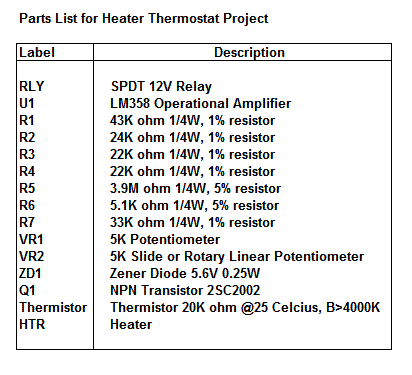
Parts List


ref: electronics-project-design.com/HVACThermostat.html

Constructing FM transmitters (89MHz - 109MHz)

This project provides the schematic and the parts list needed to construct FM transmitters with an operating frequency of 89MHz - 109MHz. You need a receiver to receive the signals from this transmitter. Typical radio tuned to FM range will be able to receive this signal.
A Frequency Modulated wave is a sine wave with a periodically varying instantaneous frequency and a constant amplitude. The average frequency is called the carrier frequency and the instantaneous frequency changes at the modulation frequency . The maximum excursion of the instantaneous frequency from the average is related to the modulation depth .
For a FM radio transmission, the carrier frequency would be the station you tune to, and you would hear a pure audio tone at the modulation frequency, with a loudness derived from the modulation depth.
Frequency modulation (FM) is the encoding of information in either analog or digital form into a carrier wave by variation of its instantaneous frequency in accordance with an input signal. This is typically accomplished using radio waves. The most typical use is radio broadcasting.
Frequency modulation requires a wider bandwidth than amplitude modulation by an equivalent modulating signal, but this also makes the signal more robust against interference. Frequency modulation is also more robust against simple signal amplitude fading phenomena. As a result, FM was chosen as the modulation standard for high frequency, high fidelity radio transmission: hence the term "FM radio". The FM modulation illustration is as shown in the diagram below.


When assembling the components into the PCB, be careful to cut the leads of components as short as possible because at high frequencies, leads will alter the capacitance and inductance of the circuits.
The output of the FM transmitters is approximately 9mW at 9V with the antenna tapped at position B. Tapping the antenna at position A will triple the range to 27mW.
You can find the CK217 9V FM Transmitters kit here under the SURVEILLANCE AND SECURITY (SPY) category.

ref: electronics-project-design.com/FMtransmitters.html

Infra Red Wireless Door Monitor

Door Monitor Project
This door monitor project uses an infrared beam to monitor door & passageways or any other area. When the beam is broken a relay is tripped which can be used to sound a bell or alarm. Suitable for detecting customers entering a shop, cars coming up a driveway, etc. The IR beam is very strong. Distances over 25 feet can be monitored. A 12VDC supply is required to power the circuit. A 12V wall adaptor is fine. Provision has been made so that only one power supply needs to be used to power both units. The relay is rated to switch mains voltages.
Door Monitor Transmitter Board


The door monitor transmitter board consists of two square-wave oscillators, one running at approx. 250Hz and the other running at 38kHz. The 38kHz frequency acts as a carrier wave and is required by the IR receiver module on the receiver board. This carrier wave is “ANDed” or modulated by the 250Hz frequency to produce an output signal that contains bursts of 38kHz at a rate of 250Hz. This signal is used to drive an infrared LED. The oscillators are made by using two 555 timer ICs set up as “astable” (free running) multivibrators. IC1 is used for the 250Hz oscillator. Resistor R1 and R2 and capacitor C1 set the frequency. Another 555 chip, IC2, is used for the 38KHz oscillator. Resistors R4 and R5 and capacitor C3 set the frequency. Notice the diodes D1 and D3. These are provided to create a “symmetrical” output. Normally the external capacitor C1 (C3) charges through resistors R1 and R2 (R4 and R5) and discharges through R2 (R5). Without the diodes this output waveform would have a longer “high” time than the “low” time. The diode bypasses resistor R2 (and R5) when the capacitor is charging, so that it is only charged via R1 (or R5). This gives the same charging and discharging time and so the output waveform has equal high and low times.
The charge time (output high) is given by:
THIGH = 0.693 x R1 x C1 (or 0.693 x R4 x C3)
The discharge time (output low) is given by:
TLOW = 0.693 x R2 x C1 (or 0.693 x R5 x C3)
The output frequency = 1 / (THIGH + TLOW)

The output from the IC1 is coupled via diode D2 and resistor R3 to the ‘trigger’ input of IC2. When the IC1 output is low it stops IC2 from running and IC2’s output is forced high (no IR LED current). When IC1 output is high, IC2 runs and the IR LED is pulsed at 38KHz.
The Waitrony IR LED is driven directly from the output of IC2. Resistor R6 sets the maximum LED current. With a 12VDC supply the current is about 45mA (the LED drops 2V across it when conducting). Lowering the value of R6 will increase the current through the LED thus boosting the signal strength. This may be necessary if the kit is used outside in direct sunlight or if you need “very long range”. Keep in mind that the maximum current that the 555 can handle is 200mA
If the distance to be monitored is less than about 10 yards then you will need to fit the 5mm shrink tubing over the IR LED. This narrows the radiating angle of the IR beam and makes it much more directional. The IR output is strong. It can easily bounce off walls etc to give false readings.
Door Monitor Receiver Board


The door monitor receiver consists of an IR receiver module that detects the incoming IR beam from the transmitter. The IR signal is used to keep a capacitor charged which in turn holds a relay operated. When the beam is broken the capacitor discharges and the relay releases. An IR receiver/detector module, RX1, is made up of an an amplifier/filter circuit tuned to detect a 38kHz frequency. The output pin is low whenever a 38kHz signal is detected.
When the IR beam is present the relay is operated. Not all Receiver Modules are the same. IR decoder module looks for a manufacturer-specific leader code before it decodes the modulated signal. The door monitor project produces an NEC compatible Leader code. The Kodenshi PIC37043LM and PIC12043LO decoder modules are the ones that are used in this project. If you use the incorrect IR decoder module the relay will not be operated continuously but will drop out after less than a second after power is applied.
The output of RX1 is the 250Hz signal from the transmitter. This signal is passed via transistor Q1, capacitor C1and diode D2 to capacitor C2. C2 is fully charged during the high portion of the signal. It starts to discharge during the low portion of the signal via LED L1, resistor R4 and transistor Q2. However the discharge time is much longer than the off time of the signal so the voltage across C2 is always enough to keep transistor Q2 on and therefore the relay operated. When the beam is broken the output of RX1 is high. Transistor Q1 is off and capacitor C2 is no longer being recharged. It will eventually discharge to the point where transistor Q2 will turn off and the relay will release. The “turn off” delay is determined by the time constant of resistor R5 and capacitor C3. With the values used it is approx. half a second. Capacitor C1 prevents a steady DC voltage on the collector of Q1 from charging C2. This would occur if the beam was not present or the beam was a continuous 38kHz signal. In other words, the receiver module will only respond to a pulsed 38kHz signal.
LED L1 gives a visual indication when the IR beam is present and is used to help with installation and setup. Zener diode Z1, resistor R6 and capacitor C4 provides a stable 5.6V supply for the IR module. The relays used should be mains rated: 250V/12A; 120VAC/15A.


Door Monitor Parts List


ref: electronics-project-design.com/DoorMonitor.html

Decoding Of Infrared Remote Control Software

Infrared Remote Control Software
This Infrared Remote Control Software project based on Microchip 16C57 microcontroller is a reference guide to decode infrared remote control signals from television, VCR, air conditioner or other home appliances handset that uses NEC 6121 infrared format. Once one is able to understand how to decode an IR signal of a certain format, decoding another format can be easily done as the flow chart is more or less the same except the timing of the new format.
The NEC 6121 format is based on pulse width timing in determining whether the data transmitted is "1" or "0". The data "1" is determined by the pulse width timing from one rising edge to the next rising edge of 2.24ms. The data "0" is determined by the pulse width timing from one rising edge to the next rising edge of 1.12ms.

Most of the transmitter are modulated using a frequency of 32.75 kHz, 35.0 kHz, 36.0 kHz, 36.7 kHz, 38 kHz, 39 kHz, 40 kHz, 41.7 kHz, 48 kHz, and 56.8 kHz. The ones that are commonly used are 38 kHz and 40 kHz. In order to decode the received signals, the corresponding demodulating receiver must be used. For instance, if a modulating frequency at the transmitter used is 40 kHz, then the receiver demodulating frequency used should be 40 kHz as well. Modulating the data is a better design as this will make the data integrity better and less susceptible to noise. The demodulating receivers can be obtained from suppliers such as Vishay, LiteOn, Sharp or Kodenshi.

One word of caution when using the IR remote control is that it is easily affected by lighting devices that emits the infrared frequency. One such example is the fluorescent tube which emits the infrared frequency in its operation. When this type of lights is operating, the receiver may not be able to receive the signal from the transmtter due to interference from the signals emitted by the flurescent tube. In situation like this, confirm this by switching off the lights when controlling the device.
You may want to consider using RF frequency as a solution in this particular location. Another way is to place a filter in front of the receiver to narrow the infrared window but this solution will compromise the angle and operating distance of the infrared transmitter.
The infrared remote control software project provides the flow chart and source code and can be downloaded from Microchip website.

ref: electronics-project-design.com/Infrared-remote-control-software.html


3 Transistor Audio Amp (50 milliWatt)

Here is a little audio amplifier similar to what you might find in a small transistor radio. The input stage is biased so that the supply voltage is divided equally across the two complimentary output transistors which are slightly biased in conduction by the diodes between the bases. A 3.3 ohm resistor is used in series with the emitters of the output transistors to stabilize the bias current so it doesn't change much with temperature or with different transistors and diodes. As the bias current increases, the voltage between the emitter and base decreases, thus reducing the conduction. Input impedance is about 500 ohms and voltage gain is about 5 with an 8 ohm speaker attached. The voltage swing on the speaker is about 2 volts without distorting and power output is in the 50 milliwatt range. A higher supply voltage and the addition of heat sinks to the output transistors would provide more power. Circuit draws about 30 milliamps from a 9 volt supply.

ref: bowdenshobbycircuits.info/page8.htm#db.gif

Telephone Audio Interface

Audio from a telephone line can be obtained using a transformer and capacitor to isolate the line from external equipment. A non-polarized capacitor is placed in series with the transformer line connection to prevent DC current from flowing in the transformer winding which may prevent the line from returning to the on-hook state. The capacitor should have a voltage rating above the peak ring voltage of 90 volts plus the on-hook voltage of 48 volts, or 138 volts total. This was measured locally and may vary with location, a 400 volt or more rating is recommended. Audio level from the transformer is about 100 millivolts which can be connected to a high impedance amplifier or tape recorder input. The 3 transistor amplifier shown above can also be used. For overvoltage protection, two diodes are connected across the transformer secondary to limit the audio signal to 700 millivolts peak during the ringing signal. The diodes can be most any silicon type (1N400X / 1N4148 / 1N914 or other). The 620 ohm resistor serves to reduce loading of the line if the output is connected to a very low impedance.

ref: bowdenshobbycircuits.info/page8.htm#db.gif

Triangle and Squarewave Generator

Here is a simple triangle/squarewave generator using a common 1458 dual op-amp that can be used from very low frequencies to about 10 Khz. The time interval for one half cycle is about R*C and the outputs will supply about 10 milliamps of current. Triangle amplitude can be altered by adjusting the 47K resistor, and waveform offset can be removed by adding a capacitor in series with the output.

ref: bowdenshobbycircuits.info/page8.htm#db.gif

Thursday, September 24, 2009

Improved 3 Transistor Audio Amp (80 milliwatt)

This circuit is similar to the one above but uses positive feedback to get a little more amplitude to the speaker. I copied it from a small 5 transistor radio that uses a 25 ohm speaker. In the circuit above, the load resistor for the driver transistor is tied directly to the + supply. This has a disadvantage in that as the output moves positive, the drop across the 470 ohm resistor decreases which reduces the base current to the top NPN transistor. Thus the output cannot move all the way to the + supply because there wouldn't be any voltage across the 470 resistor and no base current to the NPN transistor.
This circuit corrects the problem somewhat and allows a larger voltage swing and probably more output power, but I don't know how much without doing a lot of testing. The output still won't move more than a couple volts using small transistors since the peak current won't be more than 100mA or so into a 25 ohm load. But it's an improvement over the other circuit above.
In this circuit, the 1K load resistor is tied to the speaker so that as the output moves negative, the voltage on the 1K resistor is reduced, which aids in turning off the top NPN transistor. When the output moves positive, the charge on the 470uF capacitor aids in turning on the top NPN transistor.
The original circuit in the radio used a 300 ohm resistor where the 2 diodes are shown but I changed the resistor to 2 diodes so the amp would operate on lower voltages with less distortion. The transistors shown 2n3053 and 2n2905 are just parts I used for the other circuit above and could be smaller types. Most any small transistors can be used, but they should be capable of 100mA or more current. A 2N3904 or 2N3906 are probably a little small, but would work at low volume.
The 2 diodes generate a fairly constant bias voltage as the battery drains and reduces crossover distortion. But you should take care to insure the idle current is around 10 to 20 milliamps with no signal and the output transistors do not get hot under load.
The circuit should work with a regular 8 ohm speaker, but the output power may be somewhat less. To optimize the operation, select a resistor where the 100K is shown to set the output voltage at 1/2 the supply voltage (4.5 volts). This resistor might be anything from 50K to 700K depending on the gain of the transistor used where the 3904 is shown.

ref: bowdenshobbycircuits.info/page8.htm#db.gif

Decibel Meter


The circuit below responds to sound pressure levels from about 60 to 70 dB. The sound is picked up by an 8 ohm speaker, amplified by a transistor stage and one LM324 op-amp section. You can also use a dynamic microphone but I found the speaker was more sensitive. The remaining 3 sections of the LM324 quad op-amp are used as voltage comparators and drive 3 indicator LEDs or incandescents which are spaced about 3dB apart. An additional transistor is needed for incandescent lights as shown with the lower lamp. I used 12 volt, 50mA lamps. Each light represents about a 3dB change in sound level so that when all 3 lights are on, the sound level is about 4 times greater than the level needed to light one lamp. The sensitivity can be adjusted with the 500K pot so that one lamp comes on with a reference sound level. The other two lamps will then indicate about a 2X and 4X increase in volume.
In operation, with no input, the DC voltage at pins 1,2 and 3 of the op-amp will be about 4 volts, and the voltage on the (+) inputs to the 3 comparators (pins 5,10,12) will be about a half volt less due to the 1N914 diode drop. The voltage on the (-) comparator inputs will be around 5.1 and 6.5 which is set by the 560 and 750 ohm resistors.
When an audio signal is present, the 10uF capacitor connected to the diode will charge toward the peak audio level at the op-amp output at pin 1. As the volume increases, the DC voltage on the capacitor and also (+) comparator inputs will increase and the lamp will turn on when the (+) input goes above the (-) input. As the volume decreases, the capacitor discharges through the parallel 100K resistor and the lamps go out. You can change the response time with a larger or smaller capacitor.
This circuit requires a well filtered power source, it will respond to very small changes in supply voltage, so you probably will need a large filter capacitor connected directly to the 330 ohm resistor. I managed to get it to work with an unregulated wall transformer power source, but I had to use 4700uF. It worked well on a regulated supply with only 1000uF.

ref: bowdenshobbycircuits.info/page8.htm#db.gif

FM Transmitter

Here is the schematic, PC board pattern, and parts placement for a low powered FM transmitter. The range of the transmitter when running at 9V is about 300 feet. Running it from 12V increases the range to about 400 feet. This transmitter should not be used as a room or telephone bug. 
 
 
C1           1              0.001uf Disc Capacitor   
C2           1              5.6pf Disc Capacitor        
C3,C4     2              10uf Electrolytic Capacitor           
C5           1              3-18pf Adjustable Cap  
R1           1              270 Ohm 1/8W Resistor 270 Ohm 1/4W Resistor
R2,R5,R6              3              4.7k 1/8W Resistor          4.7K 1/4W Resistor
R3           1              10k 1/8W Resistor            10K 1/4W Resistor
R4           1              100k 1/8W Resistor         100K 1/4W Resistor
Q1, Q2  2              2N2222A NPN Transistor               2N3904, NTE123A
L1, L2     2              5 Turn Air Core Coil         
MIC        1              Electret Microphone     
MISC     1              9V Battery Snap, PC Board, Wire For Antenna    

  1. L1 and L2 are 5 turns of 28 AWG enamel coated magnet wire wound with a inside diameter of about 4mm. The inside of a ballpoint pen works well (the plastic tube that holds the ink). Remove the form after winding then install the coil on the circuit board, being careful not to bend it.
  2. C5 is used for tuning. This transmitter operates on the normal broadcast frequencies (88-108MHz).
  3. Q1 and Q2 can also be 2N3904 or something similar.
  4. You can use 1/4 W resistors mounted vertically instead of 1/8 W resistors.
  5. You may want to bypass the battery with a .01uf capacitor.
  6. An antenna may not be required for operation.
ref: aaroncake.net/Circuits/fmtrans.asp

Thursday, September 17, 2009

12V to 120V Inverter


Have you ever wanted to run a TV, stereo or other appliance while on the road or camping? Well, this inverter should solve that problem. It takes 12 VDC and steps it up to 120 VAC. The wattage depends on which tansistors you use for Q1 and Q2, as well as how "big" a transformer you use for T1. The inverter can be constructed to supply anywhere from 1 to 1000 (1 KW) watts. 
C1, C2    2              68 uf, 25 V Tantalum Capacitor  
R1, R2    2              10 Ohm, 5 Watt Resistor              
R3, R4    2              180 Ohm, 1 Watt Resistor            
D1, D2   2              HEP 154 Silicon Diode    
Q1, Q2  2              2N3055 NPN Transistor (see "Notes")    
T1           1              24V, Center Tapped Transformer (see "Notes")               
MISC     1              Wire, Case, Receptical (For Output)        

  1. Q1 and Q2, as well as T1, determine how much wattage the inverter can supply. With Q1,Q2=2N3055 and T1= 15 A, the inverter can supply about 300 watts. Larger transformers and more powerful transistors can be substituted for T1, Q1 and Q2 for more power.
  2. The easiest and least expensive way to get a large T1 is to re-wind an old microwave transformer. These transformers are rated at about 1KW and are perfect. Go to a local TV repair shop and dig through the dumpster until you get the largest microwave you can find. The bigger the microwave the bigger transformer. Remove the transformer, being careful not to touch the large high voltage capacitor that might still be charged. If you want, you can test the transformer, but they are usually still good. Now, remove the old 2000 V secondary, being careful not to damage the primary. Leave the primary in tact. Now, wind on 12 turns of wire, twist a loop (center tap), and wind on 12 more turns. The guage of the wire will depend on how much current you plan to have the transformer supply. Enamel covered magnet wire works great for this. Now secure the windings with tape. Thats all there is to it. Remember to use high current transistors for Q1 and Q2. The 2N3055's in the parts list can only handle 15 amps each.
  3. Remember, when operating at high wattages, this circuit draws huge amounts of current. Don't let your battery go dead :-).
  4. Since this project produces 120 VAC, you must include a fuse and build the project in a case.
  5. You must use tantalum capacitors for C1 and C2. Regular electrolytics will overheat and explode. And yes, 68uF is the correct value. There are no substitutions.
  6. This circuit can be tricky to get going. Differences in transformers, transistors, parts substitutions or anything else not on this page may cause it to not function.
  7. If you want to make 220/240 VAC instead of 120 VAC, you need a transformer with a 220/240 primary (used as the secondary in this circuit as the transformer is backwards) instead of the 120V unit specified here. The rest of the circuit stays the same. But it takes twice the current at 12V to produce 240V as it does 120V.
 ref: aaroncake.net/Circuits/inverter.asp

Dual Polarity Power Supply


This dual polarity power supply is easy to build, requires few parts, and is adjustable from 0-15 volts. It is great for powering op amp circuits, as well as other circuits that require a dual supply voltage. 

C1, C2    2              2200uF 35V Electrolytic Capacitor             
C3, C4, C5, C7     4              1uF 35V Electrolytic Capacitor    
C6, C8    2              100uF 35V Electrolytic Capacitor               
R1, R4    2              5K Pot  
R2, R3    2              240 Ohm 1/4 W Resistor               
BR1        1              2A 30V Bridge Rectifier 
U1          1              LM317 Adjustable Positive Regulator     
U2          1              LM337 Adjustable Negative Regulator   
T1           1              30V Center Tapped 2 Amp Transformer
S1           1              SPST 2 Amp Switch         
MISC     1              Heatsinks For U1 And U2, Line Cord, Case, Knobs For Pots, Wire      
  1. Since this project operates from 120 (or 220, or 240, etc.) volts AC, it MUST be built inside a case.
  2. U1 and U2 get quite hot and will require heatsinks. A fan is usually not needed.
  3. You can, of course, add a volt and amp meter.
  4. U1 and U2 can only go down to a minimum of +-1.2V. If you need to go lower, you can add two 1N4003 diodes in series with the output of the regulator. The diodes drop about 0.6V each, which will allow the supply to go to 0. Note that this will also decrease your maximum output voltage by 1.2V.
ref: aaroncake.net/Circuits/supply3.asp

Touch Activated Light


The circuits below light a 20 watt lamp when the contacts are touched and the skin resistance is about 2 Megs or less. The circuit on the left uses a power MOSFET which turns on when the voltage between the source and gate is around 6 volts. The gate of the MOSFET draws no current so the voltage on the gate will be half the supply voltage or 6 volts when the resistance across the touch contacts is equal to the fixed resistance (2 Megs) between the source and gate. The circuit on the right uses three bipolar transistors to accomplish the same result with the touch contact referenced to the negative or ground end of the supply. Since the base of a bipolar transistor draws current and the current gain is usually less than 200, three transistors are needed to raise the microamp current level through the touch contacts to a couple amps needed by the light. For additional current, the lamp could be replaced with a 12 volt relay and diode across the coil.

ref: bowdenshobbycircuits.info/page8.htm#db.gif

Simple Polarity Tester


This tester can be used to check the polarity of any power source, and is therefore very useful when installing automotive equipment, alarm systems or anything else you can think of. Because this circuit is so simple and cheap, even frying one with an over voltage is not a big deal. 
R1           1              1K 1/4W Resistor            
D1           1              Green LED          
D2           1              Red LED               
D4, D5, D6, D7    4              1N4001 Silicon Diode     1N4004, 1N4005, 1N4007
MISC     1              Board, Wire, Case, Probes           

  1. To use the circuit, just connect your probes to the source under test. If D1 lights up, the left most probe (on the schematic) is connected to positive. The opposite is true if the left probe is negative. If both LEDs are on, the source being probed is AC.
  2. Be careful when using this tester not to probe a source greater than about 12V.
  ref: aaroncake.net/Circuits/polarity.asp

Digital Keypad Combination Lock


This simple circuit is the electronic version of the combination lock. Using the special purpose LS7220 digital lock IC, the circuit allows a 4 digit combination of your choice to activate a relay for a set period of time. This relay can then be used to trigger a lock solenoid, enable a starter button, open a motorized door, or many other tasks that require a momentary signal.

               
C1           1              1uF 25V Electrolytic Capacitor   
C2           1              220uF 25V Electrolytic Capacitor              
R1           1              2.2K 1/4W Resistor        
Q1          1              2N3904 NPN Transistor 2N2222
D1           1              1N4148 Rectifier Diode 1N4001-1N4007
K1           1              12V SPDT Relay Any appropriate relay with 12V coil
U1          1              LS7220 Digital Lock IC    
S1-S12   12           SPST Momentary Pushbutton    Keypad (see notes)
HD1       1              12 Position Header        
·  To set the combination, wire the appropriate switches to U1 pins 3, 4, 5 and 6 using the header. For example if S1 was connected to pin 3, S2 to pin 4, S3 to pin 5 and S4 to pin 6, the combination would be 1,2,3,4. Now wire all other unused switches across the header to pin 2 of U1. In this way you can create any 4 digit combination you want. Pin 2 is the reset pin, so connecting all unused keys to it assures that the entire combination must be reentered if an incorrect key is pressed.
·  When the appropriate combination is entered, the relay is activated for a period of time determined by C1. The 1uF capacitor specified in the parts list will result in an on-time of roughly 5 seconds. Increase the value of C1 to increase this time.
·  An easy way to make a keypad is to buy 12 PC board mount pushbuttons and then etch a PC board so that the buttons are in 4 rows of 3, similar to a telephone keypad. Place this in a case and then use a label maker or transfer letters to add your numbers to the tops of the pushbuttons. You can also use a pre made keypad but keep in mind that you need a pad which provides an output for each key. Most pads available have the keys connected to provide a row and column signal when they are pressed.
ref: aaroncake.net/Circuits/combolock.asp

Air Flow Detector

This simple circuit uses an incandescent lamp to detect airflow. With the filament exposed to air, a constant current source is used to slightly heat the filament. As it is heated, the resistance increases. As air flows over the filament it cools down, thus lowering it's resistance. A comparator is used to detect this difference and light an LED. With a few changes, the circuit can be connected to a meter or ADC to provide an estimation on the amount of air flow. 
R1           1              100 Ohm 1/4W Resistor               
R2           1              470 Ohm 1/4W Resistor               
R3           1              10k 1/4W Resistor          
R4           1              100K 1/4W Resistor       
R5           1              1K 1/4W Resistor            
C1           1              47uF Electrolytic Capacitor         
U1          1              78L05 Voltage Regulator              
U2          1              LM339 Op Amp
L1            1              #47 Incandescent lamp with glass removed (See "Notes")         
D1           1              LED        
MISC     1              Board, Wire, Sockets for ICs, etc.             
The glass will have to be removed from L1 without breaking the filament. Wrap the glass in masking tape and it in a vise. Slowly crank down until the glass breaks, then remove the bulb and carefully peel back the tape. If the filament has broken, you will need another lamp.
ref: aaroncake.net/Circuits/airflow.asp