Lamp dimmers using traics can be quite simple, nothing more than a potentiometer, resistor, capacitor and triac with a built-in diac. The circuit below is similar to designs using unijunction transistors to generate the triggering pulse. The unijunction is replaced by a two-transistor "flasher" circuit that drives a pulse transformer. This type of circuit gives a wide range of control while exhibiting little hysteresis or line voltage sensitivity. The two diodes rectify the line voltage such that the flasher sees a positive voltage pulse on each half-cycle and, after a delay set by R and the 0.1uF capacitor, the flasher circuit triggers the triac. The capacitor discharge is deep so the dimmer starts fresh on the next half-cycle. Note that the triac always gets the same polarity of trigger pulse.
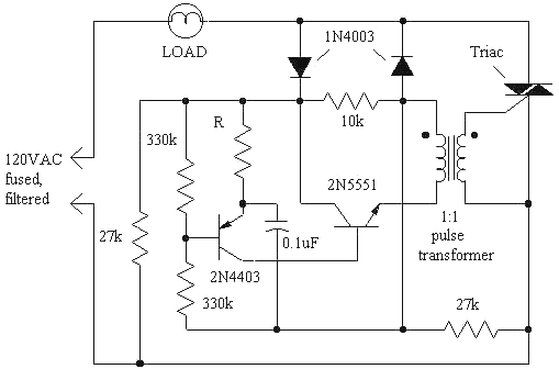
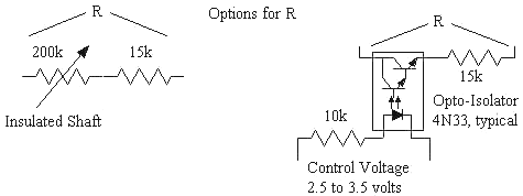
The dimmer may be controlled in a number of ways. The first option for R shows a typical mechanical control and the second option shows the use of an opto-isolator for electrically controlling the dimmer. The electronic control would be useful in applications like computer control, color organs, power flashers, heaters, speed controllers, and other feedback systems. The base of the PNP is another sensitive spot to add control but the designer must remember that the whole circuit must be floating and large voltage swings are present.
Remember, the entire circuit is "hot" and dangerous! Line power circuitry should be constructed only by qualified persons. GFI breakers are always a good idea!
The flasher could be powered from a full-wave rectified transformer secondary if line isolation is desired. Do not filter the rectified voltage or the circuit will not work properly. Use a fairly high voltage secondary, perhaps 50 VRMS to get full power control. (Lower if using a 2N4401.)
The circuit will generate significant RF noise and a line filter is recommended. (It is usually pretty easy to find potted line filters in surplus catalogs.) Also, make sure to include a fuse, as indicated.
The circuit may be used for other AC applications including motor speed control and the clever designer might add in positive feedback based on current consumption to achieve near constant motor RPM with changing load (a non-trivial challenge). Or, consider applying negative feedback via the optoisolator.
Substitutions:
The 1N4003 only see about 100 volts reverse and the current is fairly low so other rectifiers may be substituted. The 2N5551 may be replaced with a lower voltage transistor like the 2N4401 if the 10k resistor is decreased to 6.8k (to limit the collector voltage). Full brightness will be reduced a slight amount but for most applications the loss will be insignificant. The 27k resistors should be at least 1/2 watt or the resourceful experimenter may wish to double their value along with the 10k if the triac is sufficiently sensitive. The pulse transformer was designed for triggering thyristors but other types may work as substitutes - try a 1:1 phone transformer, for example.
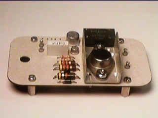
Here is a hand-made dimmer built onto a piece of laminate. The triac is an RCA T2710 and the pulse transformer is a Sprague 1:1, 66Z906. (Both are older parts from my vast surplus collection!) Read the construction page for more information about this project. Users of ExpressPCB may download the design file. The board was built into a grounded metal chassis with a line filter and fuse.


0 comments:
Post a Comment