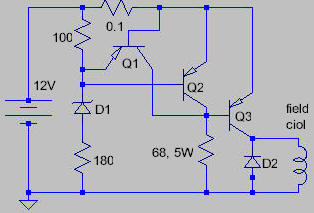
Here is an experimental (and simple!) regulator for alternator chargers. Q1 and Q2 are medium-power transistors and Q3 is a high-power type. The zener, D1 is chosen to set the charged voltage and will be about 10 volts for a 12 volt battery. The 0.1 ohm resistor sets the maximum field current. Not shown is the connection from the output of the alternator to the battery. An AC alternator will need a diode rectifier but most car types have the rectifier built in.
When the battery is low, current flows through the 0.1 ohm resistor and Q3 to the field coil. The voltage across the 0.1 turns on Q1 which limits the current in Q3 (about 0.7 / R or 7 amps in this case). When the battery is charged to about 14 volts, Q2 turns on and turns off Q3, stopping the charging.
This circuit is just a concept and has not been built and tested.
ref: techlib.com/electronics/battery_chargers.html


0 comments:
Post a Comment