The AT89C2051/ATtiny2313 evaluation board is suited well for building and testing microcontroller circuits. You can either use an AT89C2051 or an ATtiny2313, both microcontrollers are almost pincompatible, just the reset pin has different polarity. The ATtiny2313 has the advantage that it can be programmed in-circuit via SPI. Furthermore it supports On-Chip-Debugging via the built-in DebugWire interface. Debugging can be done via the reset pin with the "JTAGICE mkII" from Atmel.
The port pins are connected to terminals. A serial RS232 interface is already implemented on board which can also be disabled in order to get further port pins. A serial I²C-EEPROM can be used as a nonvolatile memory for configuration data. Via I²C-Bus other peripheral components can be connected to the evaluation board. A stabilized 5V supply is also implemented on board. 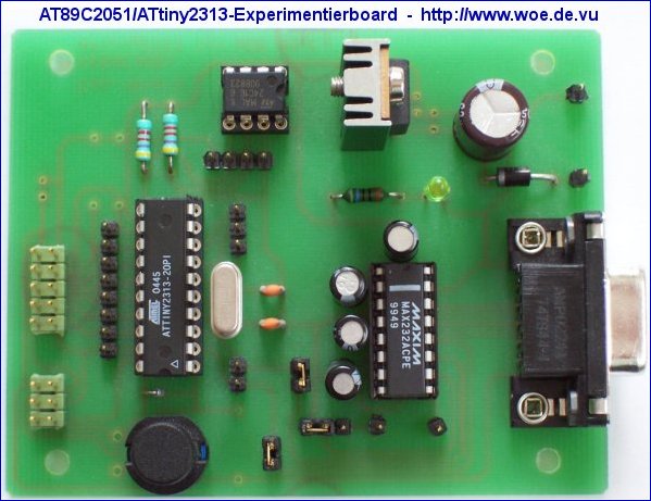
The schematic and the layout of the board can be downloaded here:
AT89C2051/ATtiny2313 evaluation board V1.1
For the hardware the freeware version of Eagle 3.55 is required. It is available for free from CadSoft.
Schematic of AT89C2051/ATtiny2313 evaluation board
Component placement of AT89C2051/ATtiny2313 evaluation board
Attention: Please consider the different component placement options according to the selected microcontroller!
There is a professionally manufactured unpopulated printed circuit board available for this project, named AT89_EXP.BRD
More information is available here: Printed circuit boards for WOE projects
Ref: woe.onlinehome.de/e_projects.htm


0 comments:
Post a Comment